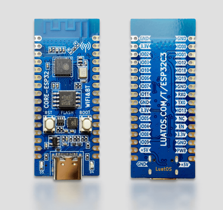
This is another ESP32 I purchased for the collection

Hardware
-
- Size length and width 21mm*51mm
- 1 way SPI FLASH, onboard 4MB, support up to 16MB
- 2-way UART interface, UART0~UART1, among which the download port is UART0
- 5 channels of 12-bit ADC, the highest sampling rate is 100KSPS
- 1 low-speed SPI interface, support master mode
- 1 way IIC controller
- 4-way PWM interface, any GPIO can be used
- 15 GPIO external pins, reusable
- 2-way SMD LED indicator light
- 1 way reset button + 1 way BOOT button
- 1 USB to TTL download and debug port
- 2.4G PCB onboard antenna
Pinout
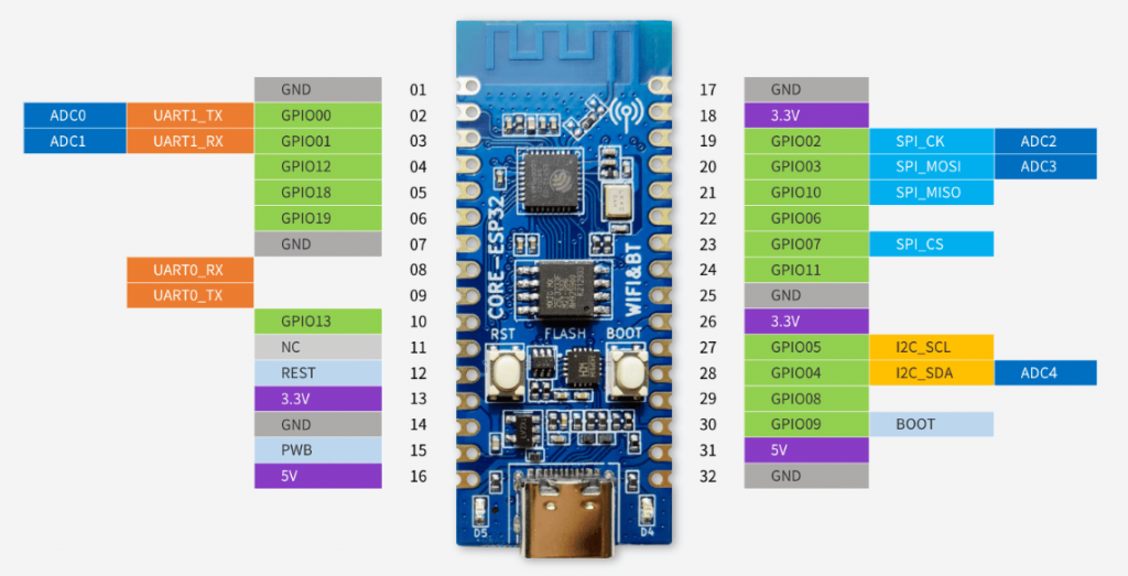
Now lets look at the pinout and functions of the board

| Pin Number | Name | Default function | multiplexing function |
|---|---|---|---|
| 32 | GND | grounding | |
| 31 | 5V | 5V power interface, connected to VBUS of USB | |
| 30 | BOOT | GPIO09, input | BOOTMODE |
| 29 | IO08 | GPIO08, input, output, high impedance | |
| 28 | IO04 | GPIO04, input, output, high impedance | I2C_SDA/ADC_4 |
| 27 | IO05 | GPIO05, input, output, high impedance | I2C_SCL/ADC_5 |
| 26 | 3.3V | Chip power supply, 3.3V | |
| 25 | GND | ground | |
| 24 | PB_11 | GPIO11, input, output, high impedance | VDD_SPI |
| 23 | IO07 | GPIO07, input, output, high impedance | SPI2_CS |
| 22 | IO06 | GPIO06, input, output, high impedance | |
| 21 | IO10 | GPIO10, input, output, high impedance | SPI2_MISO |
| 20 | IO03 | GPIO03, input, output, high impedance | SPI2_MOSI/ADC_3 |
| 19 | IO02 | GPIO02, input, output, high impedance | SPI2_CK/ADC_2 |
| 18 | 3.3V | Chip power supply, 3.3V | |
| 17 | GND | ground | |
| 16 | 5V | 5V power interface, connected to VBUS of USB | |
| 15 | PWB | Chip 3.3V power supply control, high level is effective, can be suspended when not in use | |
| 14 | GND | ground | |
| 13 | 3.3V | Chip power supply, 3.3V | |
| 12 | RESET | chip reset | |
| 11 | NC | ||
| 10 | IO13 | GPIO13, input, output, high impedance | |
| 09 | U0_RX | GPIO20, input, output, high impedance | UART0_RX |
| 08 | U0_TX | GPIO21, input, output, high impedance | UART0_TX |
| 07 | GND | ground | |
| 06 | IO19 | GPIO19, input, output, high impedance | USB_D+ |
| 05 | IO18 | GPIO18, input, output, high impedance | USB_D- |
| 04 | IO12 | GPIO12, input, output, high impedance | SPIHD |
| 03 | IO01 | GPIO1, input, output, high impedance | UART1_RX/ADC_1 |
| 02 | IO00 | GPIO0, input, output, high impedance | UART1_TX/ADC_0 |
| 01 | GND | ground |
The ESP32 core board has 2 LEDs on board that can be used.
| LED | GPIO | pin description |
|---|---|---|
| D4 | IO12 | GPIO12 configuration |
| D5 | IO13 | GPIO13 configuration |
There are two buttons on the ESP32 core board, among which the BOOT button can perform the BOOT download function, and the RST button can be used for the reset function,
| Button | pin description |
|---|---|
| BOOT/GPIO9 | When the button is pressed, the chip enters the download mode |
| RST | When the button is pressed, the chip resets |
The CORE ESP32 core board equipped with ESP32-C3 is a version without built-in FLASH, and the external SPI FLASH is mounted by default.
If you encounter a core without external SPI FLASH, you need to pay attention to the specific model of the main chip. Using built-in Flash is GPIO11/12/13not available.
| flash pin | pin description |
|---|---|
| SPICS0 | GPIO14 configuration, FLASH_CS, chip select |
| SPIQ | GPIO17 configuration, FLASH_D1, data pin 1 |
| SPID | GPIO16 configuration, FLASH_D0, data pin 0 |
| SPICLK | GPIO15 configuration, FLASH_CK, clock |
This board seems to be designed to work with a development environment called LuatIDE and LuatOS, so I will check these out but being an ESP32-C£ it will work with Arduino IDE and Micropython
Hardware Information
Schematic of CORE-ESP32-C3 development board
New version of CORE-ESP32-C3 development board schematic diagram (version without serial port chip)
https://wiki.luatos.com/pages/tools.html
