The is a 16-bit, general purpose parallel I/O port expander for I2C bus applications.
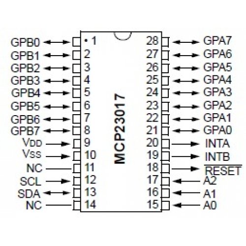
The 16-bit I/O port functionally consists of two 8-bit ports (PORTA and PORTB). The MCP23017 can be configured to operate in 8-bit or 16-bit modes. Lets look at the pinout
The MCP23017 works fine with 3.3v. So we connect VDD to the 3v3 terminal of the ESP32 module and of course we connect VSS to ground.
The GPB0-GPB7 and the GPA0-GPA7 pins are the 16 I/O ports.
NC is Not Connected.
SCL is the serial clock line. This connects to analog pin 5 on the arduino.
SDA is the serial data line. It connects to analog pin 4 on the arduino.
INTA and INTB are interrupt pins for the outputs. We are not using these here.
The RESET pin is if you want the outputs all reset to 0. We will connect this to +5V.
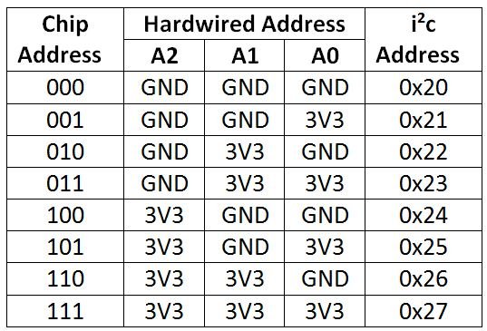
A0, A1, and A2 are the address pins. This a key thing with this device, you can in fact have 8 of these connected if you use a different address each time, this of course would give a huge amount of outputs potentially.
Here is a table of the address combinations, we will have A0, A1 and A2 tied to 0v, so that means its address 0x20
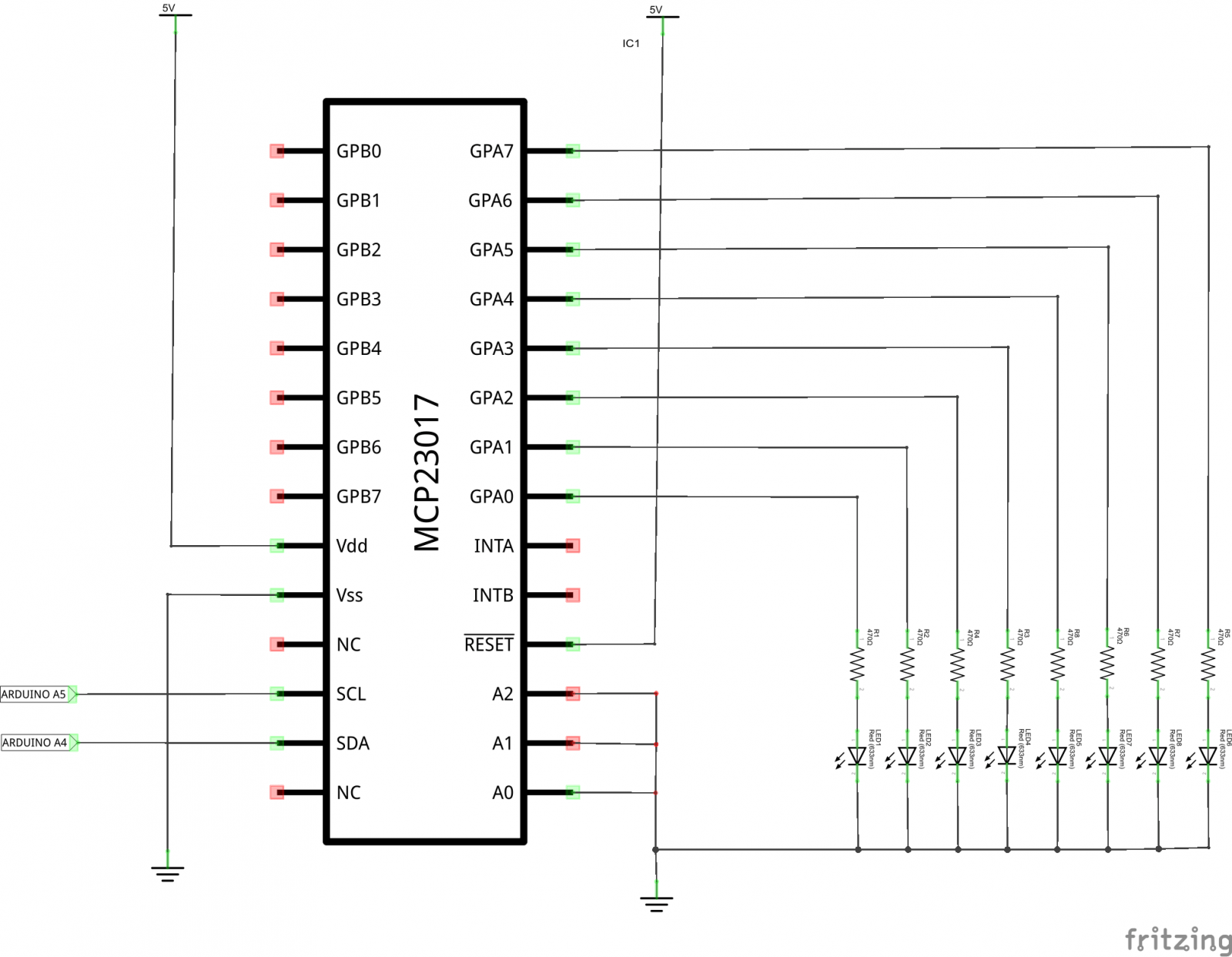
Schematic
We haven't shown the microcontroller here this shows the LED outputs only, simply connect your ESP32 I2C pins to the corresponding mcp23017 pins
You cab obviously use portb as well but would need to change the code example
Code
We are not using any library
[cpp]
#include “Wire.h”
void setup()
{
Wire.begin(); // wake up I2C bus
// set I/O pins to outputs
Wire.beginTransmission(0x20);
Wire.write(0x00); // IODIRA register
Wire.write(0x00); // set all of port A to outputs
Wire.endTransmission();
}
void loop()
{
Wire.beginTransmission(0x20);
Wire.write(0x12); // address bank A
Wire.write((byte)0xAA); // value to send – all HIGH
Wire.endTransmission();
delay(500);
Wire.beginTransmission(0x20);
Wire.write(0x12); // address bank A
Wire.write((byte)0x55); // value to send – all HIGH
Wire.endTransmission();
delay(500);
}
[/cpp]
Links
MCP23017-E/SP MCP23017 DIP28 16-Bit I/O Expander with I2C Interface IC NEW


